Learn how to setup Triplanar mapping in unreal, and some optimizations to make it run faster.
Table of Contents
- Comparison Table
- Triplanar, but with conditions
- How do we sample a texture conditionally in Unreal?
- MF_ConditionalTextureSample_Color_SharedWrapped
- MF_ConditionalTextureSample_Normal_SharedWrapped
- MF_SampleSurface_<Configuration>
- MF_Triplanar_TransformNormals_Layer
- MF_Triplanar_TransformNormals
- MF_Triplanar_Coordinates
- MF_Triplanar_BlendCoefficients
- MF_BlendMaterialAttributes_Add
- Triplanar, but with dithering
- Triplanar, but only two (Biplanar actually)
- Project Files
- Wrapping up
Triplanar Mapping (aka Box Mapping or Round Cube mapping) is a common technique in video games and has been for a long time. A lot of implementation details have been covered by individuals before in lots of different ways.
Martin Palko in 2014:

Or Ben Golus’s great medium piece from 2017 are both great starting points:

Golus’s is unity specific, so you have to do a bit of channel swizzle-ing to deal with Unreal’s Z+ Up but it is really a fantastic post, and deals with some of the intricacies around normals and blending.
Performance is always a consideration though, and despite improving hardware so have framerates and resolutions. Triplanar implies three texture samples per texture, it is pretty common these days for a single material layer in games today to use 3 textures for a single layer. This means 9 texture samples for just a single layer.
Depending on hardware, textures, other bottlenecks, etcetera this might be fine, but in the name of performance we strive to do better.
🤔 Don’t just implement anything on this page and assume you’ve made things faster. The only way to know is to actually profile your work on target hardware with representative content. It is entirely possible that in certain circumstances that these optimizations may make things worse, or much more likely, make practically no difference to performance while just introducing minor visual artifacts.
Below I’m going to go over 3 different setups, Conditional Triplanar, Dithered Triplanar, and Biplanar texture mapping. This will be more of an overview of the material functions I’ve made to do so than a direct tutorial, or a full explanation of the math/science/tech, but I will make an effort to call out any interesting bits or implementation details worth mentioning.
Each setup shares a lot of the same logic and many Material Functions, so if you jump ahead to Biplanar or Dithered Triplanar and come across something unexplained, it is probably back in the Conditional Triplanar section.
Enjoy!
Comparison Table
Use this following table for an unscientific approach to understanding how much things cost and the types of artifacts you can expect for each. Performance is counted in 🐌 because why not.
| Type | Quality | Artifacts | Performance |
|---|---|---|---|
| Triplanar | Highest | Standard Triplanar Issues | 🐌🐌🐌🐌 |
| Conditional Triplanar | Highest | Same as original Triplanar | 🐌🐌🐌 |
| Biplanar | High | Pinching and extra stretching around corners. | 🐌🐌 |
| Dithered Triplanar | Medium | Extra temporal noise around edges, especially corners. | 🐌 |
Triplanar, but with conditions

The highest quality version in this blog post, but slightly faster than the standard version.
Triplanar mapping, as noted above, is very common and a great boon to level artists a lot of the time. This whole post is mostly focused on how we can sacrifice quality for performance when dealing with triplanar. In the case of Conditional Triplanar, however, we have zero quality loss and sometimes can be a pretty large performance boost.
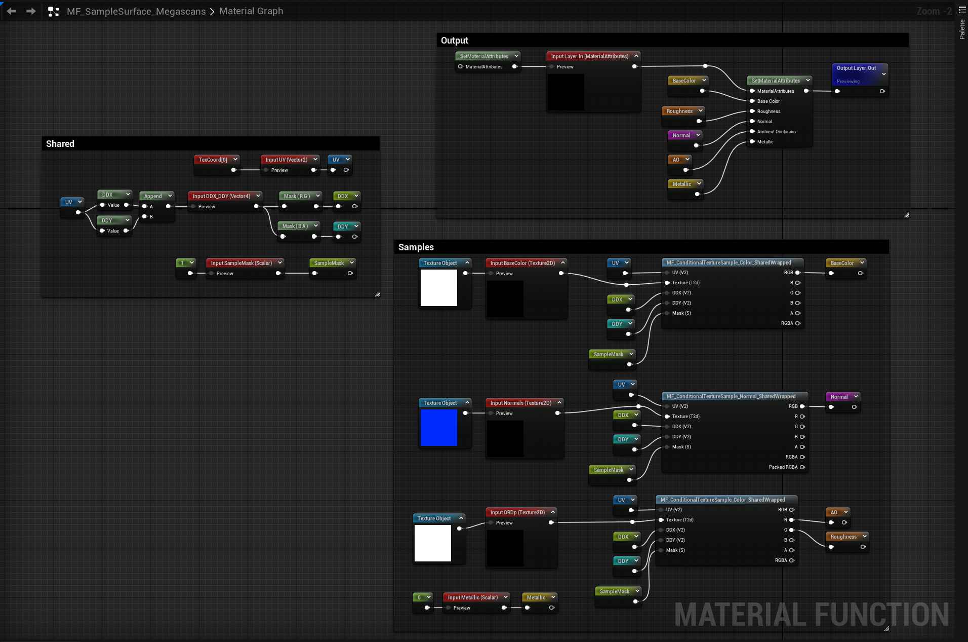
Below is the complete material graph for this effect, and below that are explanations of any material functions that are in said graph.
If you want Triplanar mapping, but don’t like noise or other artifacts, this version is the one for you.
 for full-size graph.'](./Untitled%201.png)
Click for full-size graph.
There is a lot of steps to get triplanar working in a production material, the above image is an overview of my completed function graph. I have built up of a lot of reusable parts, and a lot of sub functions to support the triplanar effect. Below I’ll go into detail about each of these functions and how I used them. But first lets talk about what makes this different from a standard triplanar material: conditional sampling.
How do we sample a texture conditionally in Unreal?
Triplanar mapping is most succinctly summed up in Inigo Quilez’s article on Biplanar Mapping from 2020 (more on that later) at the top of the article, but something that is noted at the very end is how some amount of performance could be regained by conditionally skipping samples if the blend-weights are zero.
So lets take a look at that. The first thing we need to solve is how to sample a texture (or textures) conditionally in unreal. You may have seen the If node before:

Unfortunately the hlsl for this section that is generated is converted into this:
float4 Local3 = Texture2DSampleBias(
    Texture2D_0,
    Texture2D_0Sampler,
    TexCoords[0].xy,
    View.MaterialTextureMipBias));
float3 Local5 = ((Weight.x >= 0.00000000) ? Local3.rgb : 0.00000000);
What is interesting about this is the Local5 conditional. Now it might be that a compiler could correctly do a branch at this point, but in my experience it doesn’t, it runs both sides of the conditional each time.
So we don’t yet have dynamic branching in Unreal, so how can we branch our texture samples?
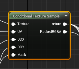
We need to turn to the custom node.
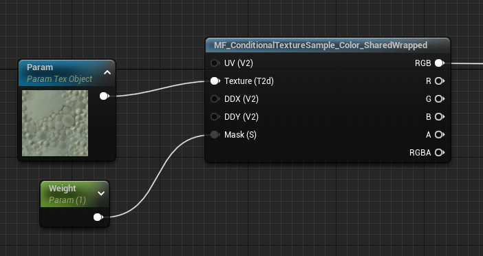
MF_ConditionalTextureSample_Color_SharedWrapped
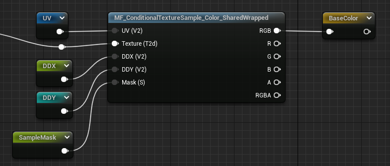
The need to be able to conditionally sample a texture makes things inconvenient. Previously we could change shared samplers, or texture type (color vs normal map etcetera) on the node, but now we are going to do the texture sampling in a custom node, and, so some of the settings the TextureSample node used to handle for us we now are handling explicitly. Switching between shared and texture samplers, compression/unpacking types, derivatives and mip biases, all of those we now need to reimplement because we want to make sure we early out of the function with a conditional.
This function’s job is to replace the texture sample node completely with a nested custom function that wraps the sample with an if(SampleMask > 0.0001) .

if( Mask < 0.0001f) return 0;

MaterialFloat4 OutTextureValue = Texture2DSampleGrad(
    Texture,
    GetMaterialSharedSampler(TextureSampler,View.MaterialTextureBilinearWrapedSampler),
    UV,
    DDX * (MaterialFloat2)View.MaterialTextureDerivativeMultiply,
    DDY * (MaterialFloat2)View.MaterialTextureDerivativeMultiply);
return OutTextureValue;
If you pass in a Texture2DObject into a custom node it automatically creates a <InputName>Sampler, but in our case we are creating wrapped textures and expect to need a fair amount of them, so it is in our best interests to use the Shared Wrapped Sampler. In a custom node you access this sampler through the View struct: View.MaterialTextureBilinearWrapedSampler
💡 We also pass in explicit texture coordinate derivatives. We do this because for some of our future versions the derivatives may not be contiguous, so we fix mipmapping issues by calculating our derivatives before selecting which axis to use. Don’t worry about it too much, but all texture samples in this post will have their derivatives calculated beforehand.
The * View.MaterialTextureDerivativeMultiply code comes from what Unreal does automatically whenever you sample with explicit derivatives, this allows you to scale the texture derivatives up and down across the whole scene.
In the project files I have also included a non-shared sampler version of this function if you need to use the texture asset’s texture sampler.
MF_ConditionalTextureSample_Normal_SharedWrapped
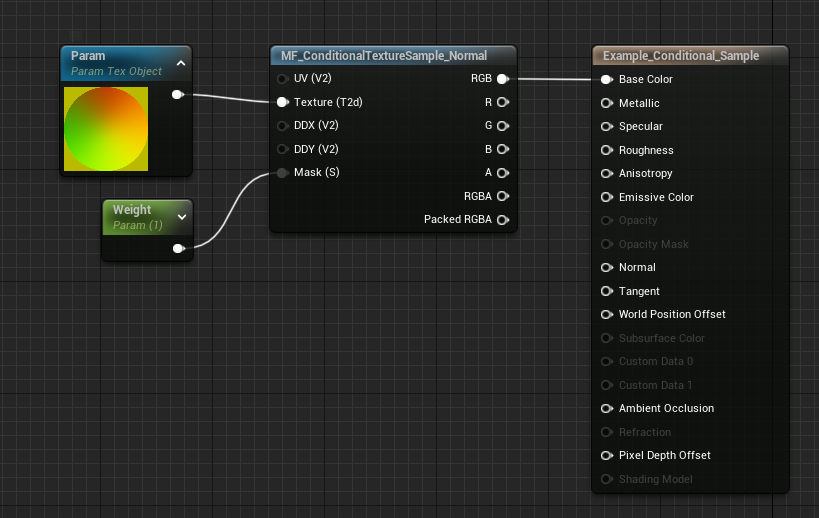
The former would cover sRGB and RGB textures no problem, but TangentSpaceNormal textures require a bit of extra work. Namely we need to call UnpackNormalMap() after sampling. We could do this in the graph, but we might as well make sure that bit of math is nested in the conditional too.
if( Mask < 0.001f) return 0;

MaterialFloat4 OutTextureValue = Texture2DSampleGrad(
    Texture,
    GetMaterialSharedSampler(TextureSampler,View.MaterialTextureBilinearWrapedSampler),
    UV,
    DDX * (MaterialFloat2)View.MaterialTextureDerivativeMultiply,
    DDY * (MaterialFloat2)View.MaterialTextureDerivativeMultiply);
PackedRGBA = OutTextureValue;
OutTextureValue.xyz = UnpackNormalMap(OutTextureValue).xyz;
return OutTextureValue;
A side benefit of wrapping your samples in a custom node is that unlike the normal texture sample node, you now don’t have to do anything different between Normalmap compressed textures and your BC7compressed textures. As long as your packed normal maps put the Normal data in RG then the result will be the same.
Since you might sometimes have valuable data in BA, this node outputs the PackedRGBA values so you can keep those around if you need them. So in a typical Normal(RG) Metallic(B) Roughness(A) setup, you’d read the RGB output pin for the unpacked normal, and then component mask BA to get Metallic and Roughness respectively.
MF_SampleSurface_<Configuration>
Material layers aren’t just individual textures, they are often a combination of textures or a texture set. Megascans for non-metal surfaces comes with BaseColor, Normals, Ambient Occlusion, and Roughness. You ****could**** put multiple texture samples into the custom nodes above, but I prefer to separate them out into individual functions, and then to bundle those together as surfaces based on texture packing, or features set.
Here is what my non-metal megascans surface packing function looks like:
These container surface functions are set up to be convenient to be used as one offs, but expect you to provide data. So while they will calculate the DDX and DDY of the UV input for you if you don’t provide your own, its encouraged to fill the inputs at the outer level so that you maximize sharing calculations.
🤔 I pack DDX(UV) and DDY(UV) into a float4 to minimize the number of pins at the outer level, but have them unpacked at the sample texture function to mirror what the regular texture sample nodes do. No other reason that organizational choices.
In my triplanar material function the usage looks like this:
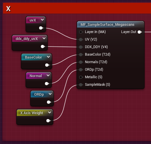
The reroutes are all for cleanliness, check the large graph overview at the top to see where each comes from.
MF_Triplanar_TransformNormals_Layer
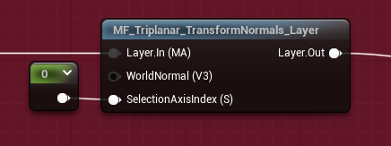
This is a convenience node actually, that takes in material attributes instead of a normal directly so we can use it in that upper level.
The node we actually care about is MF_Triplanar_TransformNormals
So now we’ve sampled the textures but we need to make sure the normals are in the right space. This is what Ben Golus’s medium post is all about, and he does a better job explaining the why then I’m going to bother trying to do, so go there if you want to know the why.
We’re just going to take his work and utilize it for ourselves.
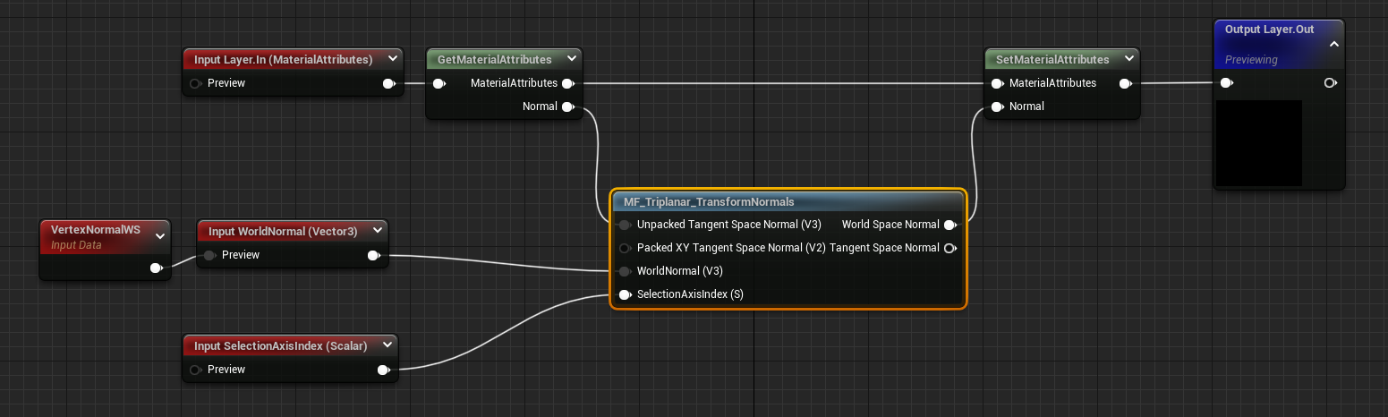
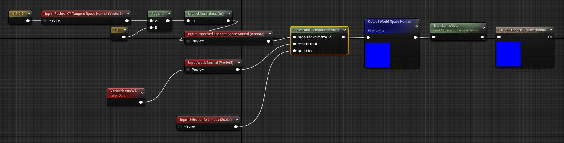
MF_Triplanar_TransformNormals
 for full-size graph.'](./Untitled%2012.png)
Click for full-size graph.
💡 Before we dive into the SelectAndTransformNormals node, I want to call out a bit of what the inputs and outputs are doing here. They are almost all for convenience.
Often users may not unpack their normal maps if they are dealing with channelpacked normals and other data, so I offer an optional Vector2 Packed XY Tangent Space Normal this then routes directly into the UnpackNormalmap() provided in hlsl before entering the second input, Unpacked Tangent Space Normal.
If Unpacked Tangent Space Normal is connected, then the Packed XY Tangent Space Normal will not be evaluated.
I take advantage of this fact a lot, this allows me to create static bool like functionality without the need for static bools. Hook up the node differently, get different behavior.
Similarly, after the World Space Normal Output I have a TransformVector World → Tangent and a secondary output. This adds a convenient way to get the tangent space normal without having to do the transformation each time. It is just there to make an shader artist’s life easier.
The meat of this function is the custom node in the center. SelectAndTransformNormals.
float3 tN = unpackedNormalValue;
int index = trunc(selection+0.001);

float3 swizzled_normals;

if( index == 0 )
{
    swizzled_normals = float3(tN.yx + worldNormal.zy, tN.z * worldNormal.x).zyx;
}
else if( index == 1 )
{
    swizzled_normals = float3(tN.xy + worldNormal.xz, tN.z * worldNormal.y).xzy;
}
else if( index == 2 )
{
    swizzled_normals = float3(tN.xy + worldNormal.xy, tN.z * worldNormal.z).xyz;
}

return normalize(swizzled_normals);
This function is almost verbatim taken from Ben Golus’s post, the only major difference is that in that post he is using a Y+ Up coordinate space, while we are using a Z+ Up space, so we need to swizzle the [0] normals from tN.xy + worldNormal.zy to tN.yx + worldNormal.zy a minor difference, but necessary to keep the correct orientation for our textures when looking down the X axis.
The other, more major, difference is that I conditionally take only one of the different swizzles based on a selection index. For the selection index, which is calculated externally, I add a small value and truncate to int so that I avoid the scenario where selection is 1.999999999 instead of 2.0 .
This makes this function work for all of the different axis which will be very important when we get to the dithered version.
What this function is doing, however, is taking the XYZ direction in tangent space of the normal, and is swizzle transforming it into their respective world axes. Golus’s post goes into it much better than me, so again, go there.
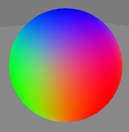
It can be hard to show why this is so important. Without this node the normals are transformed by their triangle face’s tangent space, this creates seams, but more importantly it makes the normals just wrong. In the above gif there is a light on the left side of the screen. Without the transform node the shadows are all over the place and there is a huge seam at the UV shell borders.
This is extremely important because if you don’t do this transform: your work will be subtly wrong, and it may take you a long time to notice why nothing is lighting properly.
MF_Triplanar_Coordinates
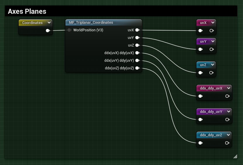
We almost have everything we need. But there is a major step we’ve skipped, and that is getting the coordinate planes for each axes. This is trivial to do, but there is a minor optimization we can do so it is worth calling out.
]
]
float3 ddxP = ddx(worldPos);
float3 ddyP = ddy(worldPos);

uvX = worldPos.yz;
uvY = worldPos.xz;
uvZ = worldPos.xy;

ddx_ddy_uvX = float4(ddxP.yz, ddyP.yz);
ddx_ddy_uvY = float4(ddxP.xz, ddyP.xz);
ddx_ddy_uvZ = float4(ddxP.xy, ddyP.xy);

return 1;
Getting the different plane UVs doesn’t need to be done in a custom node at all, but it makes the graph a lot more compact and readable. It is simple enough, we are outputting a uv coordinate based on the world position, just swizzled. Like before we’ve switched uvX to be yz instead of zy, but otherwise it is your standard setup.
The only thing maybe confusing is the ddx_ddy stuff. Again with real triplanar, we don’t actually **need** to precalculate the ddx_ddy, the shader will do this itself when we do a simple texture sample, and because each sample is partitioned from one another this is fine. We absolutely will need to precalculate the derivatives when we get to biplanar or dither, but we technically didn’t need to here for triplanar.
Except that deep inside iquilez’s article: Biplanar Mapping from 2020 there is a great little optimization. Instead of calculating ddx(UV) ddy(UV) for each axes, 6 times on 2 channels each, we can call it just twice on 3 channels each. We do this by calling ddx(worldPos) ddy(worldPos) instead of on UV, then we swizzle the results for use later. This will likely make absolutely no difference in total performance, but its cool, and I like it.
This function takes in a world position, which is where any offsetting or scaling should be done. For example:
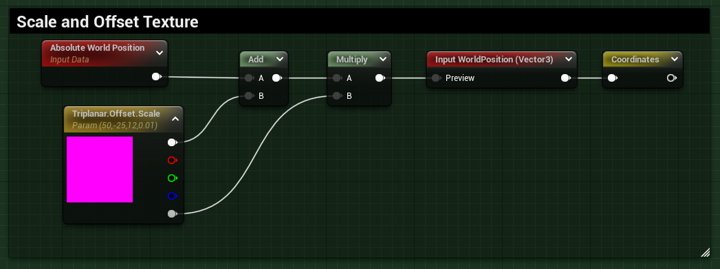
MF_Triplanar_BlendCoefficients
Getting the different blend weights for each UV plane of the triplanar mapping we do through another function:
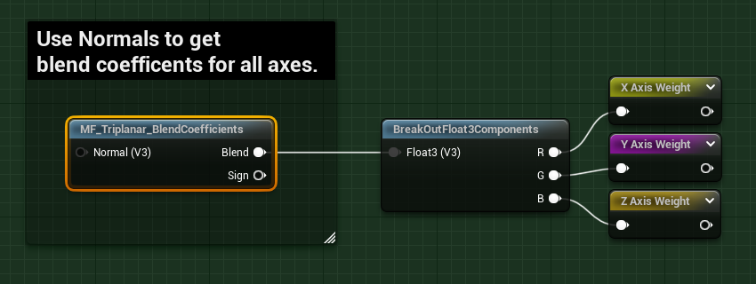
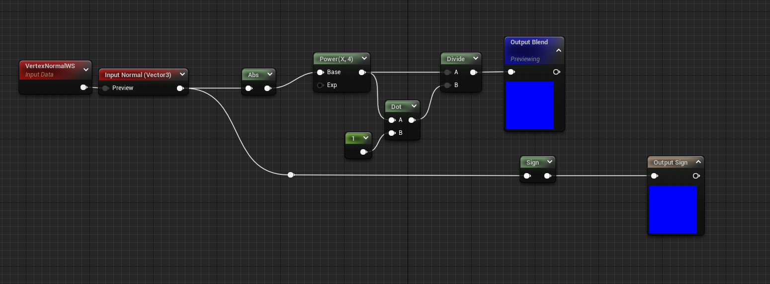
This is another bit of code taken directly from Golus:
float3 blend = pow(abs(normal), 4);
blend = blend/dot(blend, 1);
return blend;
This creates a semi sharp falloff on the edges of the three axes. There are lots of other ways to create a blend. I wrap my blend math in a function so it is reusable, the output being a float3 where each channel corresponds to the weight of each axes.
🤔 Be careful with the pow() function here, in HLSL negative base values in pow(base, exp) are NaN and Epic just clamps the values to the positive range for safety reasons. I’ve burned so much time because I’ve forgotten this. Use abs on any values that go into a pow or learn to feel regret like me.
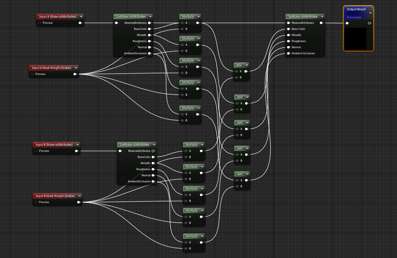
MF_BlendMaterialAttributes_Add
The final function we need to put everything together is a function to blend the different samples.
 for full-size graph.'](./Untitled%2020.png)
Click for full-size graph.
Because our blend weights are sum normalized (the above blend = blend/dot(blend,1) ) the way we expect to blend the different samples is a simple set of adds and multiplies sampleX * blend.x + sampleY * blend.y + sampleZ * blend.z . Unfortunately Unreal doesn’t currently have a blend mode in Blend Attributes to do either adds nor multiplies so we have to expand it all out manually.
It is a huge pain, one that I intend to rectify at some point in the future.
Since we are using this function, which notably only takes 2 input layers, we need to use the blend function twice. And when we handle the second one we need to make sure that we don’t over blend away the first layers:

Setting the A Mask Weight to 1.0 ensures we don’t reduce the total luminance, since those values were already scaled previously.
Triplanar, but with dithering
Here is the thing about triplanar, for each texture you need you are sampling three times. As layers increase this can get out of hand fast.
Here is the thing about Unreal, we are tied invariably to Temporal AA as it is, and the number of things that tie us to temporal convergence increases every year. So despite being someone who considers TAA a necessary evil, here I am throwing more sacrifices on its altar.
If we are tied to TAA anyway, why not use it to reduce the triplanar texture sampling per texture from three to one.
🤔 As before, test on your hardware with your actual content, because there are circumstances where this could make things worse, or more likely, not any better.
 for full-size graph.'](./Untitled%2023.png)
Click for full-size graph.
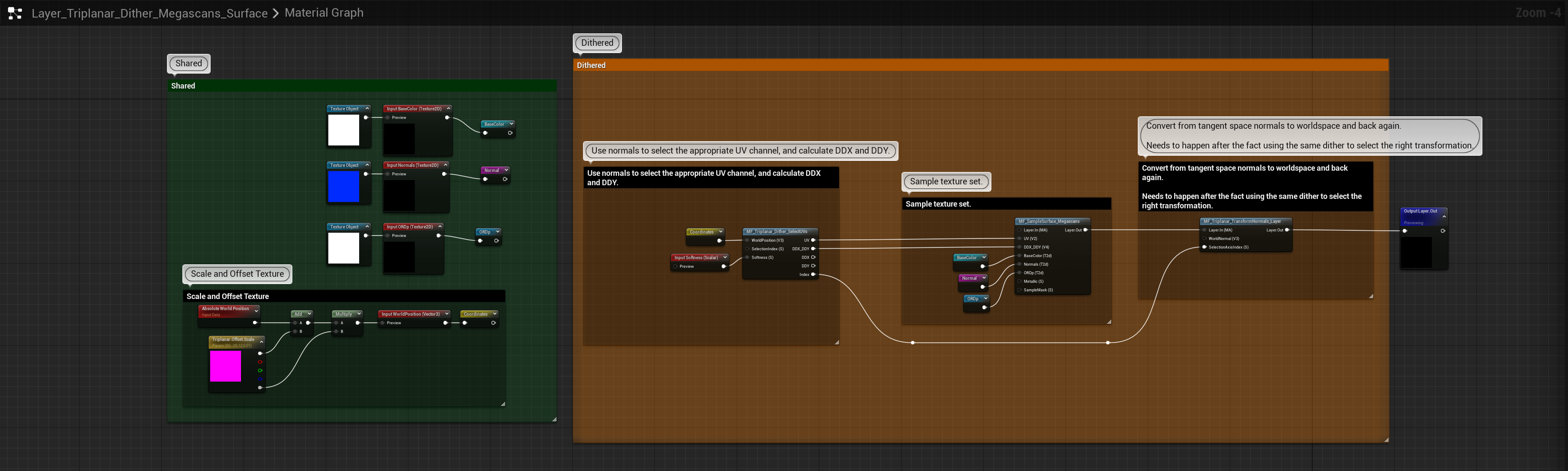
The structure is not too dissimilar to the full Triplanar version, but there are a few differences.
Most notably there is only one MF_SampleSurface being used, but also some of the calculations we did before out side in the ‘shared’ section we are now doing inside a new material function.
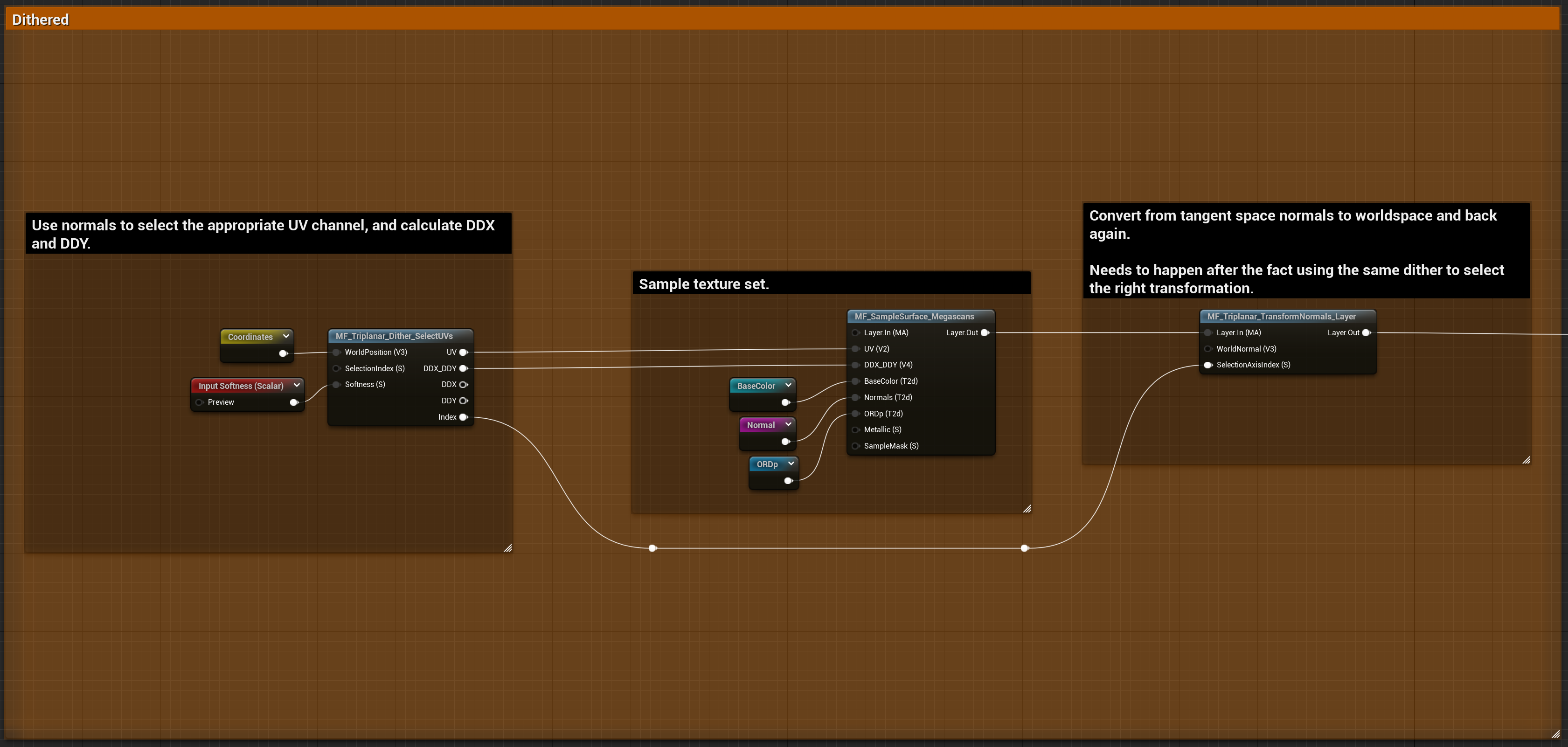 for full-size graph.'](./Untitled%2024.png)
Click for full-size graph.
The right half of this graph is the same, we use MF_SampleSurface and run the output into the MF_Triplanar_TransformNormals_Layer only this time instead of using a constant value as the SelectionAxisIndex we are piping in a previously calculated value from a new function.
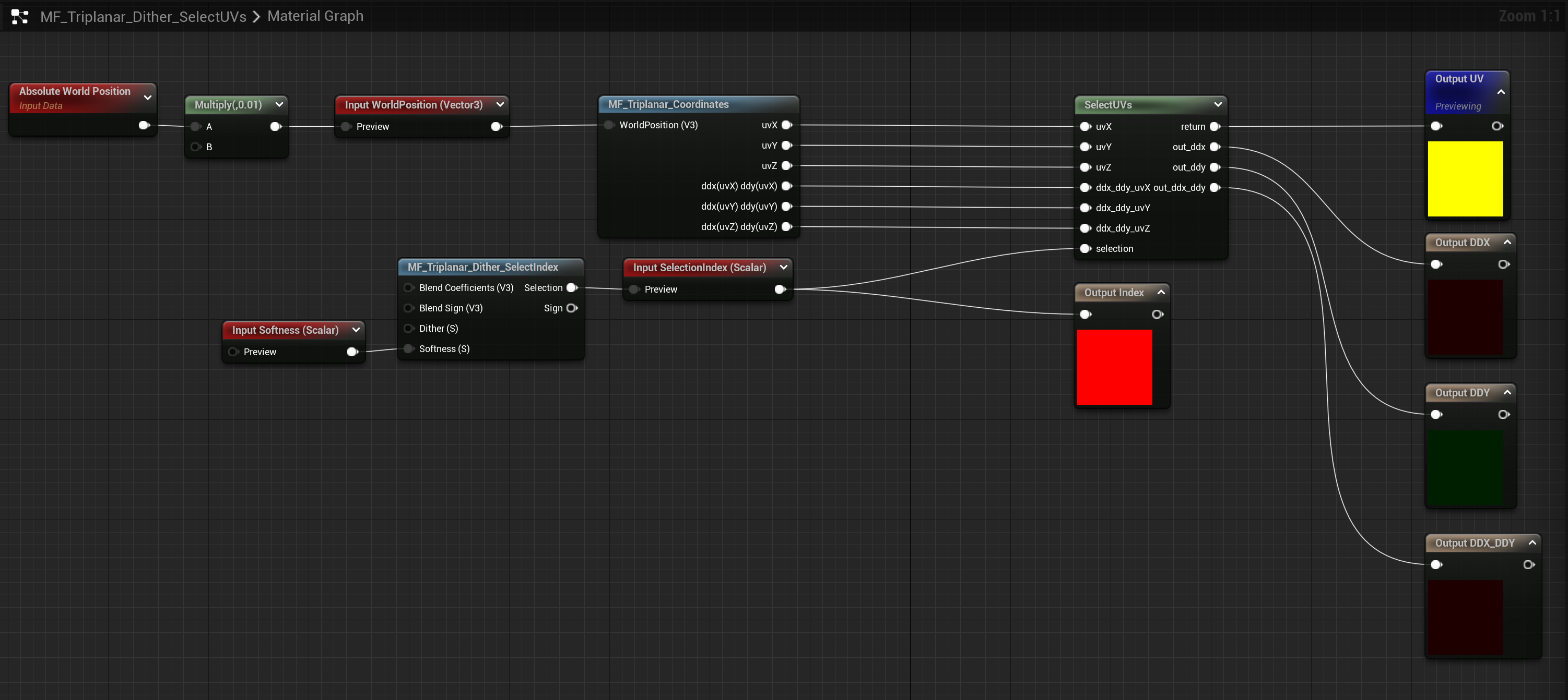
MF_Triplanar_Dither_SelectUVs
 for full-size graph.'](./Untitled%2025.png)
Click for full-size graph.
We are going to work are way backward like we did before. This node wraps the TriplanarCoordinates node from before which it passes into a SelectUVs custom node.
💡 As an implementation detail you could pull the MF_Triplanar_Coordinates outside of this function and pass in all the values, especially if you were say using full triplanar for one layer, but dithered triplanar for another.
This custom node takes in a selection index (more on that later) just like the transform normals did before, only this time it is outputting one of the axes and one of the derivatives.
int index = trunc(selection + 0.01f);
float2 uv_choices[3] = {uvX, uvY, uvZ};
float4 uv_choices_ddx_ddy[3] = {
   ddx_ddy_uvX,
   ddx_ddy_uvY,
   ddx_ddy_uvZ
};
out_ddx_ddy = uv_choices_ddx_ddy[index];
out_ddx = out_ddx_ddy.xy;
out_ddy = out_ddx_ddy.zw;
return uv_choices[index];
Since I’ve implemented the derivatives and uv generation externally, I chose to just use float2[2] and float[4] arrays to store this data and do the selections rather than if statements. I can’t imagine there is any real substantial difference between the two, but feel free to reimplement this section however you want to.
The int index = trunc(selection + 0.01f); is again to prevent possible float issues where selection is 1.999999 instead of 2.0.
The FunctionInput SelectionIndex has a default value that uses our next important dithering function:
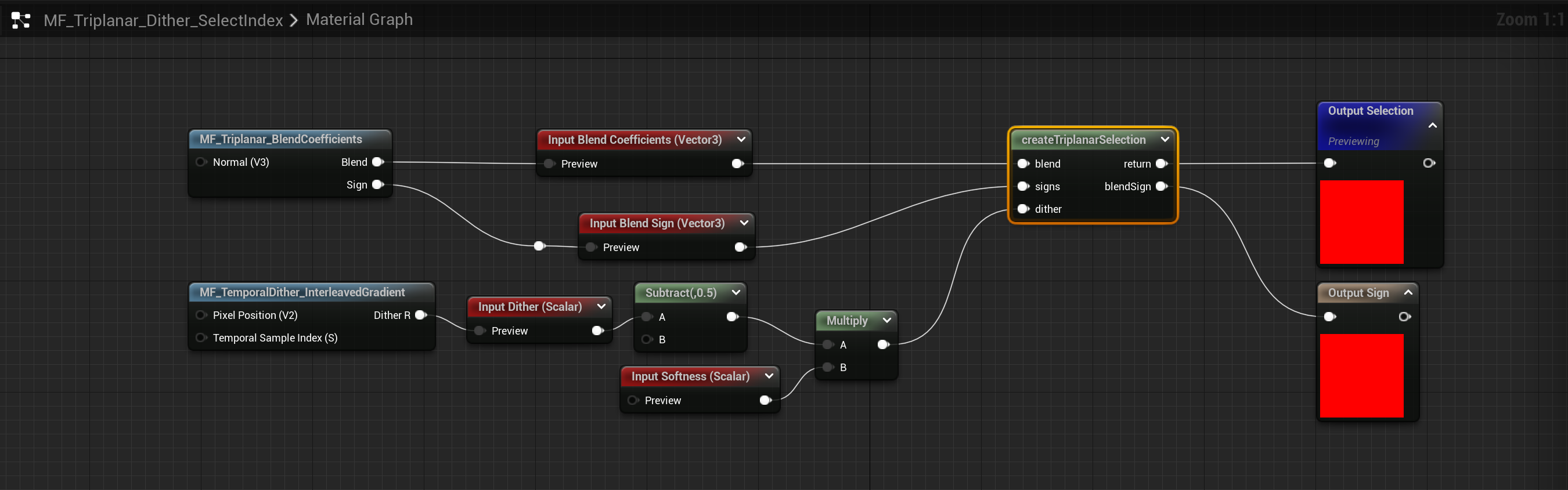
MF_Triplanar_Dither_SelectIndex
 for full-size graph.'](./Untitled%2026.png)
Click for full-size graph.
This node wraps yet another simple custom node, in this case we are taking the blend coefficients (by default generated by MF_Triplanar_BlendCoefficients) modifies the blend value by a dither value (by default MF_TemporalDither_InterleavedGradient) and picks the largest value.
blend = saturate(blend);
float index = 0;
index = blend.x - dither > blend.y ? 0 : 1;
index = blend.z - dither > max(blend.x, blend.y) ? 2 : index;

blendSign = signs[index];
return index;
There isn’t much to that, but specifically this node works the same regardless of what dither algorithm you use, which is why the dither is an input instead of being part of the custom node here.
Interlude: Picking a dither function.
A temporal dither is a screen based per-pixel random value. Ideally the noise pattern is ‘blue’ across spatial coordinates, and ‘blue’ across temporal coordinates. There are a lot of different ways to generate such noises.
For example Spatiotemporal Blue Noise which uses a texture array (or flipbook) of noises that have flat energy across multiple frames.

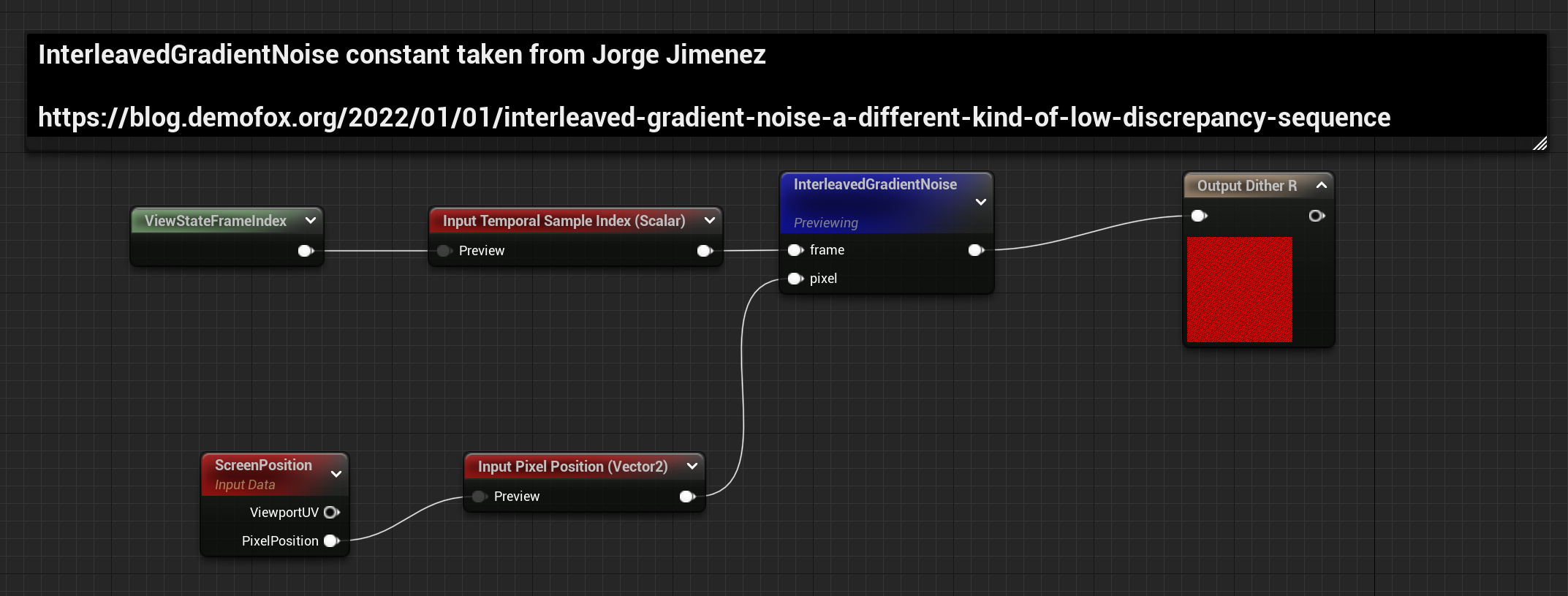
Or perhaps Interleaved Gradient Noise:

The built in DitherTemporalAA function in unreal can work in a pinch too, but its temporal characteristics are pretty lacking, and the randomization function creates a lot of hot and cold spots in the noise texture.
In more recent UE versions a new TemporalSobol node has also been introduced which in theory should work a bit better:
But I’ve noticed these strong vertical and horizontal streaks.
🤔 It is possible I am not using this node correctly, as in the past I didn’t notice any such issues, but I think I may be missing something about its intended usage.
I’ve tried all of these options. SpatioTemporalBlueNoise has the least grain for sure, but it also requires a precomputed texture and there still is some visible tiling. So I’ve gone with InterleavedGradientNoise. All credit here goes to Alan Wolfe and Jorge Jimenez for their work here.
MF_TemporalDither_InterleavedGradient
 for full-size graph.'](./Untitled%2031.png)
Click for full-size graph.
There are two important pieces, first the actual noise. Since the material graph works with floats only; I do a bit of house cleaning to ensure I get the same values that the authors of this technique would’ve gotten.
int f = trunc(frame)%64;
int2 iP = trunc(pixel);
pixel = float2(iP) + 5.588238f * float(f);
return  frac(52.9829189f * frac(0.06711056f*pixel.x + 0.00583715f*pixel.y));
Secondly, we need to get a frame value. This isn’t exposed anywhere in any material functions that I know of, but we can get it from a custom node. ViewStateFrameIndex is its own custom node that just grabs the StateFrameIndex
View.StateFrameIndex;
Triplanar, but only two (Biplanar actually)
Dither has potential issues with GPU cache thrashing (or something something mumble muble), so a different version was proposed by Inigo Quilez where only the two highest weighted planes are used instead of all three:

This removes any of the dithering noise artifacts present in the dither version, and (due to some clever math Quilez provides in his post) only has some minor issues when the three weights are near equal at the corners.
My solution is near identical to his, but with support for transforming normals, something his post doesn’t go into, and where I’m using the conditional samples again to allow reduction down to only one sample in a lot of cases.
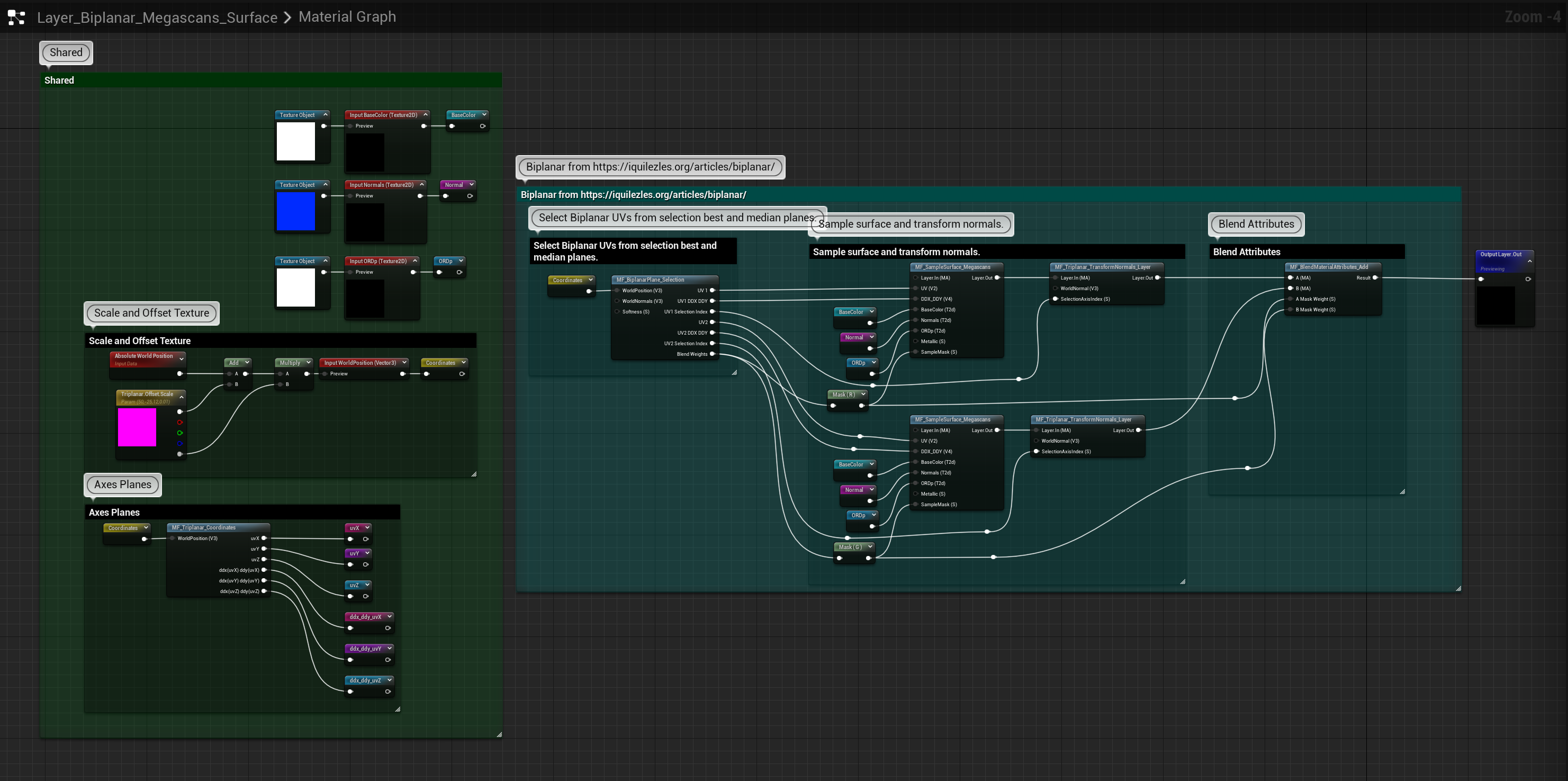 for full-size graph.'](./Untitled%2035.png)
Click for full-size graph.
Structurally this follows the original Triplanar setup, but notably with only one MF_BlendMaterialAttributes_Add and with an additional node MF_BiplanarPlane_Selection at the start which selects the UV axes and derivatives for the two texture samples.
MF_BiplanarPlane_Selection
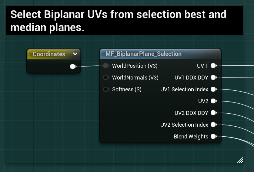
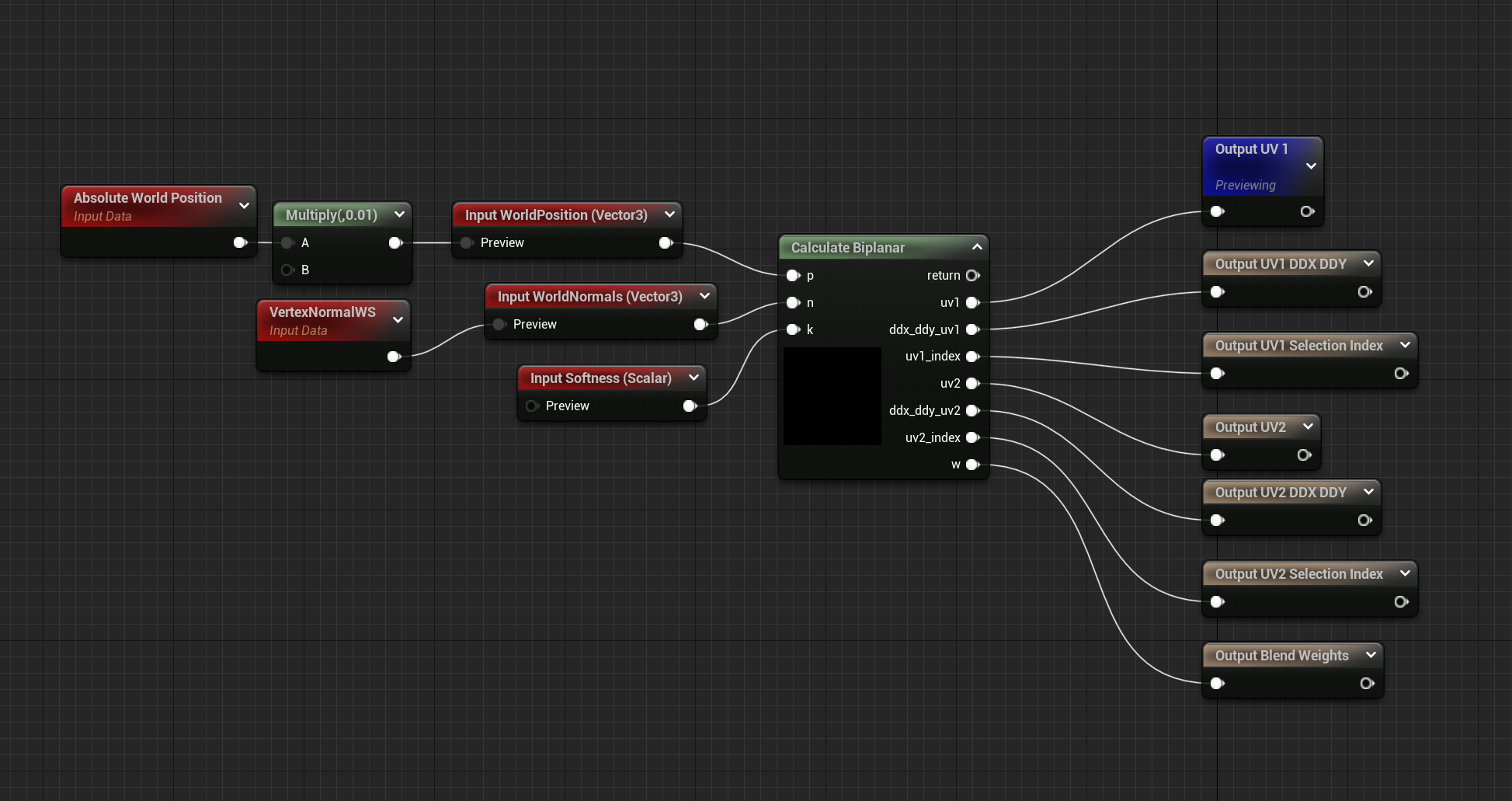
As with most of these functions, this comes down to a Custom node. Refer to Quilez’s article for the reasons why, but here we are selecting two sets of UVs and Derivatives, one for the primary sample and one for the secondary sample.
We have several outputs, UVs, Derivatives for the maximum and median axes. We also output the axes index for both so we can transform the normals appropriately. Finally we output the calculated blend weights for the blend after sampling.
// from iquilez https://iquilezles.org/articles/biplanar/

float3 dpdx = ddx(p);
float3 dpdy = ddy(p);
n = abs(n);

// determine major axis (in x; yz are following axis)
int3 ma =   (n.x>n.y && n.x>n.z) ?  int3(0,1,2) :
            (n.y>n.z)            ?  int3(1,2,0) :
                                    int3(2,0,1) ;
// determine minor axis (in x; yz are following axis)
int3 mi =   (n.x<n.y && n.x<n.z) ?  int3(0,1,2) :
            (n.y<n.z)            ?  int3(1,2,0) :
                                    int3(2,0,1) ;
// determine median axis (in x;  yz are following axis)
int3 me = int3(3,3,3) - mi - ma;

uv1_index = ma.x;
uv1 = float2(   p[ma.y],   p[ma.z]);
uv1 = ma.x == 1 ? uv1.yx : uv1;  //unreal Zup, swap coordinates if index 1
ddx_ddy_uv1 = float4(dpdx[ma.y],dpdx[ma.z], dpdy[ma.y],dpdy[ma.z]);

uv2_index = me.x;
uv2 = float2(   p[me.y],   p[me.z]);
uv2 = me.x == 1 ? uv2.yx : uv2; //unreal Zup, swap coordinates if index 1
ddx_ddy_uv2 = float4(dpdx[me.y],dpdx[me.z], dpdy[me.y],dpdy[me.z]);

// blend factors
w = float2(n[ma.x],n[me.x]);
// make local support
w = clamp( (w-0.5773)/(1.0-0.5773), 0.0, 1.0 );
// shape transition
w = pow( w, k );
w /= dot(w, 1);
// blend and return
return 0;
The calculation of the median and maximum axes is exceptionally clever IMO, I had attempted to come up with my own solution but found the solution I had come up with far too complicated to continue with. Inigo’s solution is clean and easy to understand.
If you are following along with Inigo’s article there are some changes to call out.
I’ve removed the k/8 term in the blend values, I also am clearly not sampling the textures in this function, instead I am outputting all these values so that I may sample textures later.
Finally after getting uv1 and uv2, if we are in the Y axes (ma.x == 1 || me.x == 1) I swap the xy channels to yx of the UVs to account for Unreal’s Zup+
Check out the full graph image for more, but it is important to make sure the Mask Weights end up Blend function, and the Selection Index in the Transform Normals function.
We can squeeze a bit more performance out of this function by also conditionally sampling our layers only when their weights are greater than zero.
Since the SampleMask for the Maximum will always be above zero, this will never get stripped out, but the median value may often have a weight of zero, so in most cases we will only be sampling one full layer, and expecting the branching to skip the others. (As always, hardware and content depending).
Project Files
All the project files for this post are available below. However, because I’ve used megascans textures and meshes as my examples, and the terms of service of the megascans does not allow me to distribute those files directly, installation takes a few steps.
This content was generated in Unreal Engine 5.0.2 it is not backwards compatible directly due to asset Object Versions.
How to Install
- If you wish to see and use my examples, then in the UE5 Megascans Bridge Plugin download the following two files:
-
Download the project files here:
Last Updated 11/09/2022 -
Extract these into your content folder. Everything is arranged inside of the developers folder
!['Untitled']()
- You may at this point wish to move the entire folder to a new location and fixup redirectors. I leave this up to you.


How to Use
This project is not designed to be ready to slide instantly into any production, I also cannot guarantee any support. Texture packing, compression and a variety of other differences your project may have compels you to modify my functions to work with your setups.
However, it is meant to be a good starting point, so in that regard:
- Start by looking at the Examples
**ExampleMaterial_Collapsed** uses **Layer_** functions which wrap everything you’ve seen above. These are the most plug-and-play there is.
2. **ExampleMaterial_Expanded** uses the same logic (more or less) but where the contents of those **Layer** functions has been brought out. This can help you quickly compare the differences between the different methods.
3. These instances have static switches for each method, with the default being Triplanar.
- Use the PerfTest materials on your target to see if even in a stripped down case there is any benefit. This is not sufficient to know for sure, but it is a good starting point.
This material has a checkbox for each of the different types, including triplanar with out the conditionals. It also samples the layers multiple times with different world positions to try to get an idea for the worst case. This is not representative of your actual materials/textures and does not account for a different texture set at each layer, but it gives you a decent starting point and is easily modified to build your own tests. 3. Change or replace the **MF_SampleSurface_Megascans** it is probable you have a separate set of texture packing requirements, the idea is that you would make your own (or modify mine in place) function that wraps all the texture packing.
Wrapping up
I love triplanar mapping and I think you should too. Hopefully if you work in unreal this thread has helped you. Personally I’ll probably use biplanar mapping the most in the future, but idk, depends on what happens.
If you have comments or thoughts hit me up at one of the various social medias!
https://twitter.com/RyanDowlingSoka
https://mastodon.gamedev.place/@ryan_dowlingsoka
https://cohost.org/RyanDowlingSoka
Or you can most likely find me at benui’s or asher’s discords.