Learn how to use vertex animation to make pendulum motion for hanging environmental props or vegetation.
A small segment of the Gears 5: Hivebusters DLC using the techniques in this blog post.
Table of Contents
Hanging from a thread.
This technique can be used for anything that needs to hang like a rope with a weight at the end, doesn’t need to physically interact with anything, and just needs to do cool stuff. Vines and Ivy, pendants, windchimes, incense holders, pig-heads: all are equally good candidates.
Anecdote time:
While working on Gears 4 I was tasked with intensifying all of the tree, bush, and vine animations in our game so that they looked better in hurricane level winds. This work I basically redid in Gears 5, and has mostly survived into Hivebusters. What this did though, was teach me all the ways you can make things look like their moving in the wind, and I learned a very valuable lesson from this.
💡 Trees blowing in the wind look a lot like hanging pendulums.
Why might be a bit counter-intuitive. In a pendulum: the return to the center is driven by gravity, as the pendulum moves through its arc, it returns to the center because gravity is always pulling down. This slows the speed of the pendulum, stopping its forward velocity and reversing it.
For a tree, standing straight up, but getting blown over in the wind: what returns it to the center? Elasticity. The tree has grown straight up and has built in material elasticity that keeps it from falling over. When a great buffet of wind blows forward, it might bend the tree over, but unless the wind is continuous or strong and consistent enough to overcome the elasticity and replace it with plasticity, the tree will return to its upright shape.
These are the same effect, only the speed and consistency of a hanging object returning to the center is more consistent than a tree trunk.
Let us focus on pendulums now, but keep in mind how these same behaviors might be used for something standing upright too.
The components of a pendulum.
The behavior of a pendulum seems complex but it can be broken down into a few parts.
Primary Rotation
First there is the primary rotation. This is the behavior of the pendulum in a vacuum. nothing causes the pendulum to slow down along its length, so the whole thing rotates as if it were a rigid rod. In a vacuum, the speed of the pendulum on earth would be directly tied to how much it rotates. But, no one cares about facts and no one wants a pendulum in a vacuum, so screw that. We will always just pick a good looking believable speed.
First we need to just get a sine wave going, we need to get values for rotating back and forth.
For convenience, and because we’ll need this same setup a few times, I’ve made a function just to wrap a sine wave and do some period and offset functionality. In this case it is called tutorial_wave.
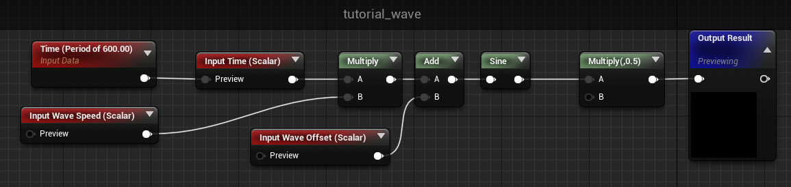
Really simple stuff, but lets break it down. We take time and multiply it by an optional Wave Speed (this changes the frequency and period of the wave, where higher numbers mean it will oscillate faster) and add an optional Wave Offset to that time value too. We put that into a sine (set to the unreal default of period == 1 second) and multiply the result by 0.5
That last multiply is just for convenience, but the reason I choose to do this is because the sine wave’s output is always -1 to 1 and that means that the total delta between the min and max of the wave is 2.0. I’d prefer that the delta be 1.0 for convenience reasons. Later, I’ll be multiplying this wave by an angle in degrees, and I’d like the angle to be the total amount the pendulum will swing back and forth. So making the wave go from -0.5 to 0.5 helps me out a bit here.
This isn’t that important, and you can skip this step, but I prefer to just do it here.
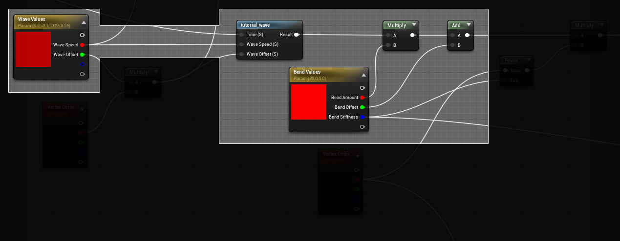
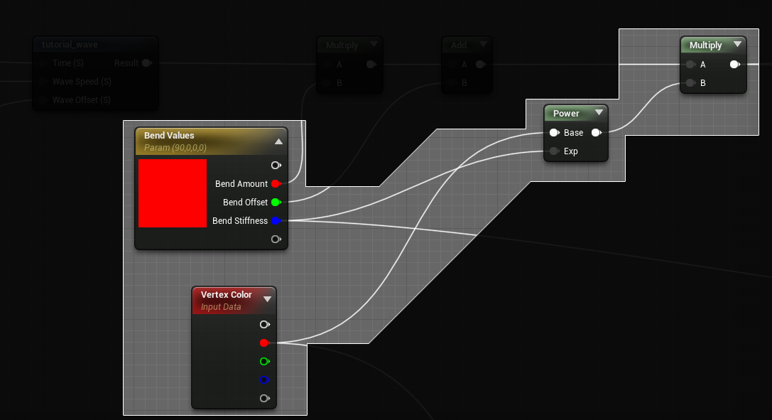
This gets hooked up into our material like so, we take some parameter values for the wave speed and offset, (more on wave offset later) and multiply the output of the wave by another material parameter, Bend Amount. We then add a Bend Offset (optional, and for heavy wind scenarios, more on that later too,) and move on with our lives. This value will go into a Rotate About Axis node.
I’ve also wrapped the Rotate About Axis expression in a material function to help with adding rotations together.

Rotate About Axis was designed to output the delta from the Position input to the new rotated location. This means you can’t just plug it directly into another rotate about axis, you need to add the positions together again. It also means that if you are trying to use the rotated position and compare it against a world-space location you will again need to add the output together with the starting position. It can take a bit to wrap your head around, but following this pattern makes it functionally similar to composing multiple rotation matrices together.
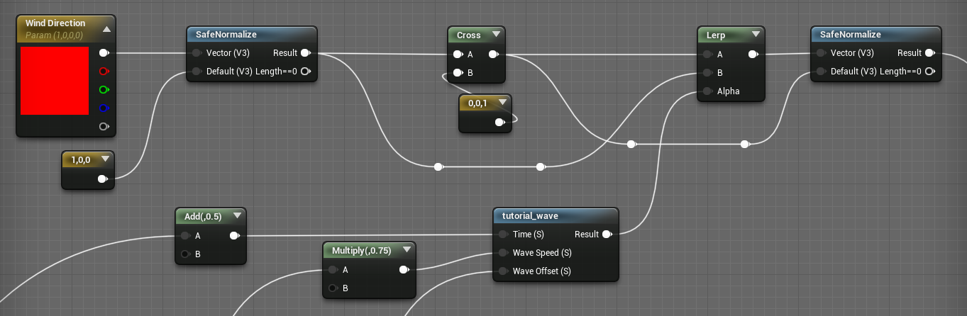
Lets take a look at the simplified setup:
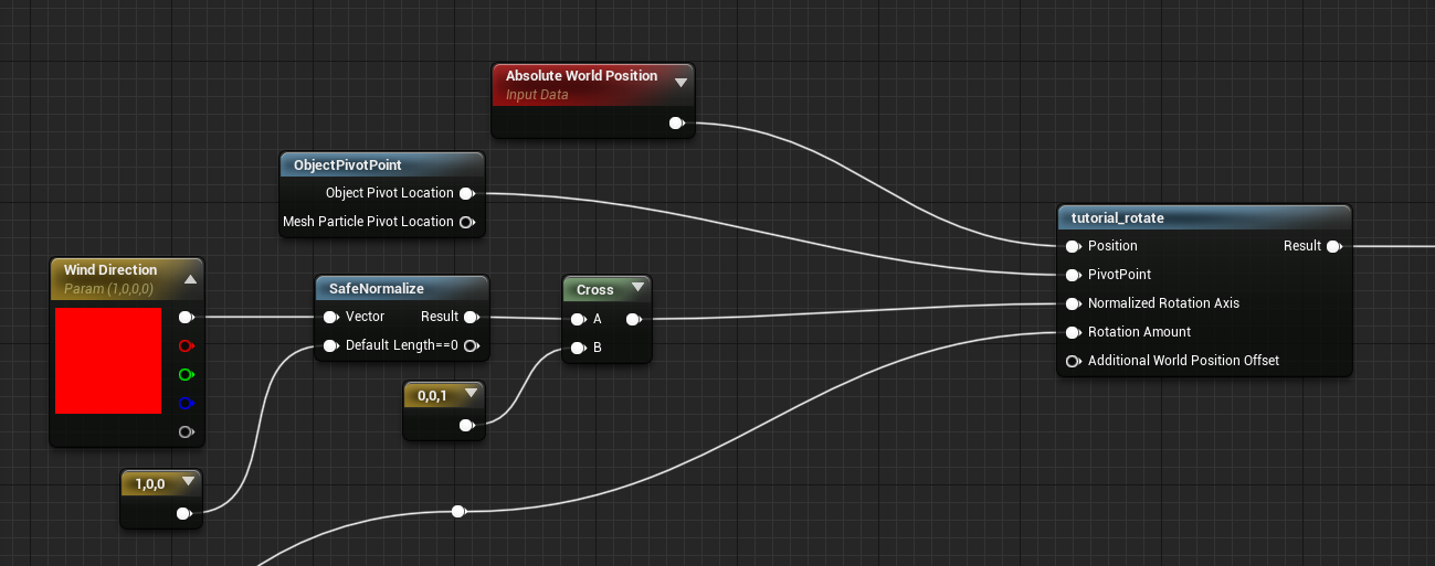
The position input will be our absolute world position, the pivot point will be the generated ObjectPivotPoint function (This is 0,0,0 transformed from Local Space to World Space). We take a Wind Direction parameter (this could be from anywhere) and cross it with the up vector. I’m using safe normalize to protect against someone putting in 0,0,0 and honestly: you should too. Dividing by zero is bad, avoid it, or be like me in the last week before shipping a title scouring material functions for why your foliage is exploding.
The cross product between the Wind Direction vector and the up vector gets you the angle perpendicular to the wind. This is the axis we want to rotate around. The output of the tutorial_rotate node can go directly into world position offset.
Air resistance.
It is unlikely you care about how a pendulum works in a vacuum anyway, so the first thing that matters to us is air resistance. This is how much force the air is exerting on the pendulum as it moves through it.
Something you may have noticed from the clip above, is that the tip of the pendulum moves a lot faster through space than the pivot. This makes intuitive sense just by looking at it. The angle of rotation is always the same in the above example, but the distance from the pivot increases along the chain.
An interesting fact about air-resistance is that the amount of force the air exerts on an object moving through it increases as the object’s speed increases. So the pig-head in our example will have the most friction applied to it.
Again, with this very simplistic setup, you could probably be all fancy and accurate about it, but no one wants that, so we are going to cheat. We will just make the end of the pendulum lag behind the pivot by offsetting it’s time in the sine wave.
What is especially fun about this method is that they way you determine how much lag to contribute can create really trippy effects, and change the feeling of the materials of the object substantially. This pig now looks like it is made of a a goopy sponge instead of a hard object. Gross. But also…. awesome. Technically, we are breaking volume preservation with this, since the rotations of the tips don’t take into account the reduced rotation of the mesh above it. But in this case, no one has ever complained. :P
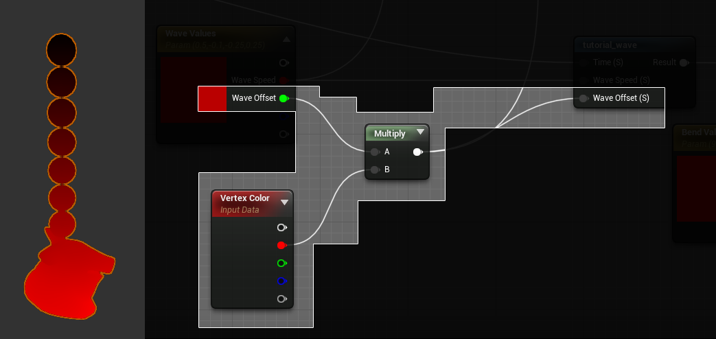
This is where the Wave Offset from before comes in. By taking a bend mask (in this case stored in the red vertex color channel) we can multiply this by an arbitrary offset and add it to the time that is passed into the sine wave.
Cross axis rotation.
So far the alignment of the rotation has been pretty straightforward. There isn’t anything so far that is causing rotation to be off of its aligned axis. But in non perfect environments it is likely that the starting conditions would not be so perfectly aligned. The rotation therefor would be more like a circle, and oval, or a figure-eight. (Check out these awesome pendulum drawings to see how cool pendulums are.)
To simulate this effect we will take the angle of rotation we are using for the rotation, and offset it a bit with a different wave. I prefer the figure-eight types, so that is what I am creating here, but ovals are also super plausible with similar setups.
In the simple version we just use the cross product of the up vector and the wind direction, but that only gives us one angle. The trick to create this figure eight like behavior is to oscillate the rotation axis between the wind direction and the cross product of the wind direction and the up vector.
This is a second wave, with a small time offset (half the sine wave period) and a reduction of the wave speed (but pulling off the Wave Speed parameter).
Just like with the air-resistance, we add the wave offset into the tutorial wave, so there is some lag as the pendulum changes direction.
Which brings us to our next super important (in my opinion, the most important) improvement to this type of animation.
Local twisting.
Air resistance has one more major effect on a pendulum, and that is turbulence. Air isn’t uniform, there are eddies, air flow, movement, and other real science words. In this case it just causes turbulence. You can add turbulence a ton of different ways, but I find the most believable looking way with pendulum motion is just to add some local twisting to the chain. By layering this twisting with the other components you can create a really believable look of turbulence affecting the pendulum.
Taking a look at the setup, first thing we need is a different wave:
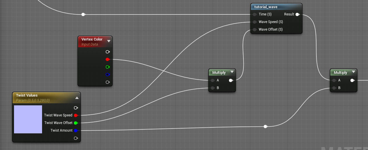
This twisting wave is like the bending wave, outputting a total angle. The lag is also similar, it is done by multiplying the bend mask (R channel) against the Twist Wave Offset. In this case though, you might want to use higher numbers, since you might want a few twists throughout the wave.
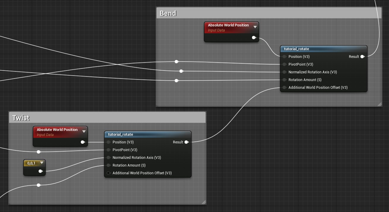
This gets plugged into the tutorial_rotate again, only this time the normalized rotation axis is set to the up vector. The pivot point is the same, though because the up vector is (0,0,1) the Z value doesn’t matter at all. As a note, if you want to be able to rotate your mesh, this isn’t going to work, you’ll need to transform the up vector into world space first.
At long last, tutorial_rotate comes into play, the output of the twist gets plugged into the bend’s Additional World Position Offset.
Ugh. Lighting and Normals.
Welcome to the bane of vertex animation. Normals.
For those unaware, a normal is a vector that describes the direction of the surface for lighting purposes. You likely have noticed that the lighting seems to move a lot for all of the clips above. There is a simple reason for that: The normals are still the same as if the pig chain wasn’t moving at all.
In some cases, you may find you actually want this behavior, for example when the amount of movement isn’t that much, and having the lighting shift more might exaggerate the movement a bit. Other times, it just isn’t noticeable so you can ignore it.
For us though, it has gotten out of hand. There are a few ways to deal with this, but I’m going to stick to the one that works the best in Unreal when dealing with the Rotate About Axis node.
🤔 If Matrices were better supported in the Unreal Material Graph, then I would recommend using matrix multiplication for this exact issue. A fair amount of computation can be avoided by multiplying the position and the normals by the same rotation matrix. You can technically do this all in custom nodes, but I’m not getting into that here.
Do everything again, this time for normals.
The theory is simple, because so far everything is just rotations, we just rotate the normal the same exact way.
An unfortunate thing about unreal is that by default we don’t have access to the Normals interpolator in the vertex shader. We can use a Vertex Interpolator to make sure the normals are updated in the vertex shader, and so hopefully some of our calculations are reused, but I’m not entirely convinced they will be, because the vertex shader operations are all functionalized, and not embedded in the same way that the majority of the pixel shader graph is.
This isn’t a big deal, and even running the operations in the pixel shader wouldn’t be the worst, just wasteful. If I cared more I would take look in pix or render-doc and confirm whether or not we are saving those sweet sweet cycles, but really…. I don’t care that much.
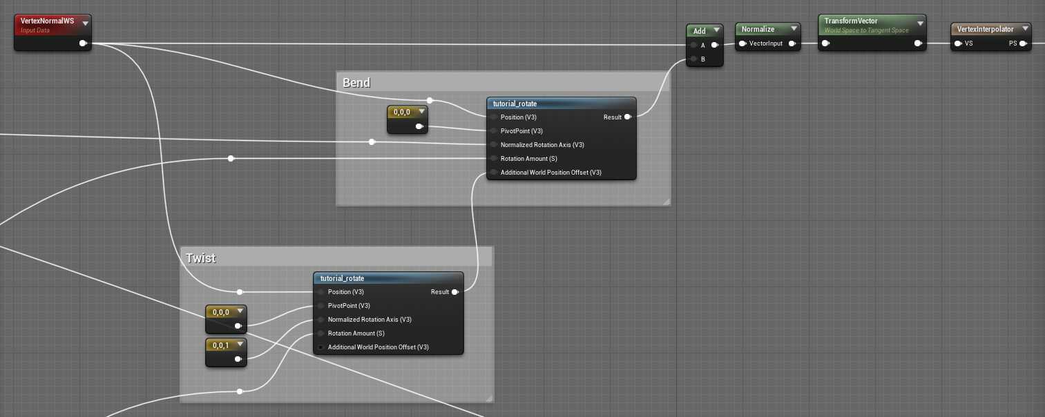
The main difference between updating the normals and updating the positions, is that instead of using the world position and the pivot of the whole chain, we use the vertex normal and a pivot of 0,0,0.
We then have to add the output of the bend rotate back against the starting vertex normal (remember, the rotate nodes return a delta, not the final location). And we should normalize it again. Just like before we either need to transform it from world space to tangent space, or disable the tangent space normals in the material.
You can blend it with a tangent space normal map if you do the transform by using the node BlendAngleCorrectedNormals.
Quick Hack (DDX cross DDY)
There is a simpler way, that is cheaper too, that does have some drawbacks. But I think I would be remiss to not mention it here.
Taking the DDX and crossing it with the DDY of the Absolute World Position (after shader offsets) returns a normalized vector for each face.
Unfortunately this removes any soft normals, and instead creates a hard-faced normals.
Remember to either use a TransformVector WorldSpace to TangentSpace before plugging this into the Normal output, or turn off the Tangent Space Normals flag in your material.
The obvious issue is facetted normals. The DDX cross DDY method simply can’t support smooth normals, so use it only where the artifacts aren’t an issue, where you want facets, or where you simply can’t use any other methods.
💡 If you happen to know a way to use a similar method and get smooth normals… please tell me. Otherwise, I’m going to just keep upping the vertex count. Add enough triangles and you can’t see the facets anymore.
Variations
When dealing with any form of animation, it is unlikely you want all your hanging pendulums to be in sync with each other (although that could be quite surreal in the right circumstances).
This is definitely what you are here for, right?
One easy way to add variation is to offset the time cycle for each instance based on their world position (this can also be useful to approximate wind gusts, but that is for another blogpost.)
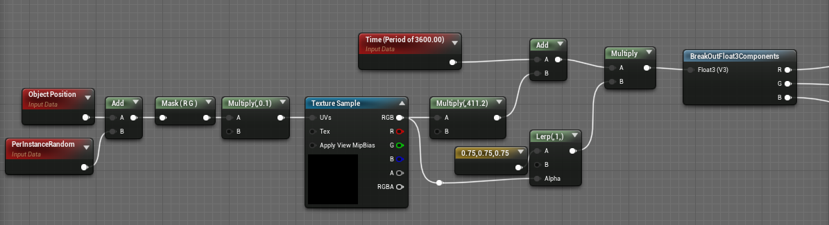
The XY components of the Object Position are as the location example for a Blue Noise RGB texture. The results are multiplied by an arbitrary value to create an arbitrary offset in time, and added to a global time.That global time is also multiplied by this same noise value but linearly interpolated between 0.75 and 1.0. By scaling time in this way different variations will have different speeds, creating additional variation.
For convenience, the time is set to a period of 3600 (1 hour) simply to prevent floating point precision errors for the cost of a pop once an hour. Seems like a good trade.
🤔 You could do it the right way, where you ensure that the fractional part of time is always in sync and you never have any pops. But I’ve never found it worth the effort when a pop-once-an-hour is so easy, and will never be noticed.
The new scaled and modified time values are then split by component and each sent to one of the three different waves.
Heavy Wind
In really really strong winds, the pendulum may never be able to return to the original center. The Bend Offset parameter from before can be used to help with this. The main trick is to lessen the total amount of bending (meaning a smaller, Bend Amount, but an increased Bend Offset, so the average position of the pendulum is always in a bent over position.
In this example I set the Bend Offset to 60, and the Bend Amount from 120 to 45, and then increased the Wave Speed from 0.5 to 1.0.
That basic setup of a bend offset added to a negative to positive bend amount was exactly what we used in Gears to handle directional bending.
Stiffness
Something I’ve left out is the concept of stiffness. With the above examples this hasn’t really been necessary to deal with. But for trees it is vital. The bottom of the tree (or the top of a pendulum made of a stiffer material) shouldn’t rotate at all. This is easy to deal with, simply use our vertex color ramp to reduce the angle of rotation. You can also multiply the WPO output if you want, but that doesn’t work as well for the normals, so it is better to multiply before the Rotate About Normals nodes.
The problem with this type of masking is that it breaks all forms of volume conservation. Now, the tips of the mesh will be rotating more than the base of the mesh. This creates shearing. Luckily with some hackery we can kind-a fix that problem too.
The basic stiffness setup is quite simple. Lets take the Bend Stiffness parameter and use it as the exponent of a power on the bend mask. This is the core of adding stiffness, a value of 1.0 creates a linear falloff of the stiff masking, a value of 0.0 results in no masking of the rotation.
Fixing the shearing is a bit more complicated, and a bit of a hack.
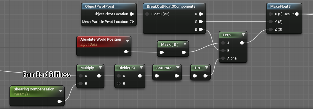
Where in all the simple versions we just used the ObjectPivotPoint, now we need to do something a little more complicated.
Here we now use the Bend Stiffness value to offset where the pivot point actually is. Our trick is to move the pivot point towards the world position based on how stiff the animation is. The Shearing Compensation scalar is a convenience one to blend the value back towards 0 (and therefor back towards the real object pivot point.) This reduces the total amount of animation, but does a good job of bringing the shearing back in line. Especially when dealing with high stiffness values, or high bend values.
So long, till next time.
Thanks for reading this far! Hopefully there is some useful information in here. If you want to take a look I’ve packaged the example above up with comments and things and stuff, and who knows: it might even be helpful.
Get the materials here.
If you have thoughts, opinions, or ideas you want to see explored, hit me up on the socials: